I am busy at the moment designing and building the electrical control box for the twin and when that is complete 'and safe!!' I will be attempting further live tests on the engine. I am fitting a multi plug and socket arrangement on the box and on the engine so they can both be completely disconnected from each other and the loom.
Propane tests have been done and it makes a lovely DEEP roar when struck up with this :) It will not actually self sustain under Propane but it's there to get everything hot before actually running the liquid fuel.
Friday, November 16, 2007
Thursday, October 25, 2007
Propane injection valve.
Just added a few more pictures of the Propane injection valve in the side of the CC.
The flame is lit before starting. I have tested to see if the starter motors running the compressor turbines put out the flame and they don't. It seems to work very well. The idea is to start the engine with the flame ignited inside the CC/FT to ignite the liquid fuel quickly thus eliminating fuel pooling.
The flame is lit before starting. I have tested to see if the starter motors running the compressor turbines put out the flame and they don't. It seems to work very well. The idea is to start the engine with the flame ignited inside the CC/FT to ignite the liquid fuel quickly thus eliminating fuel pooling.


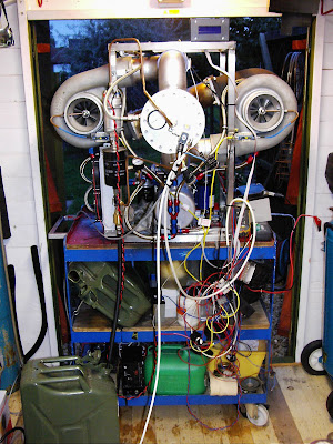
Picture from the shed door looking inside :)

Wednesday, October 17, 2007
The completed system.


This device below is to be the start solenoid injector. It is off of the choke start from a Ford engine and will serve the purpose well. I have to decide whether to fit it next to the main nozzle or next to the igniter plug to spray fuel or Propane for starting only. The solenoid will only operate when the igniter is lit thus igniting whatever fuel I decide to use.


This device below is to be the start solenoid injector. It is off of the choke start from a Ford engine and will serve the purpose well. I have to decide whether to fit it next to the main nozzle or next to the igniter plug to spray fuel or Propane for starting only. The solenoid will only operate when the igniter is lit thus igniting whatever fuel I decide to use.


Fitting the CC drain
I needed to fit a combustion chamber drain so I got a 1/4bsp coupler and cut it in half. I then drilled a suitable hole in the bottom, front of the CC.


I then TIG welded the coupler to the CC and added a shortened right angle pipe olive gland.


I then TIG welded the coupler to the CC and added a shortened right angle pipe olive gland.

This feeds down into a 12v solenoid and out to a fuel drain canister (eventually)

Monday, October 15, 2007
Propane start system and CC drain valve
I have come to the conclusion that during the start up the other weekend I had a 'run away' situation caused by excess unburnt fuel pooling into the combustion chamber bottom caused by the fuel not igniting quick enough thus allowing it to fall to the bottom of the CC.
SO.....
I have been tinkering in the shed again this evening and found what I think may be the answer to my starting system problem. I have taken a video of what it is and how it's too work, below. It's a cold start (choke start) solenoid spray valve from a Ford engine. It's been sat in my 'fuel bit's' draw for ages and it just caught my eye as I was ferreting through earlier. If I add low pressure propane to the fuel in end and supply 12vdc to it it has a lovely wide spray of propane emit from the end. I have decided to fit it right next to the igniter plug so it sticks into the CC side wall and sprays more or less straight onto the plug. The 12v supply to the said solenoid will be taken from the igniter feed so that whenever the igniter is excited, so is the gas valve thus firing any liquid fuel almost instantaneously.
I have also found that I can indeed find enough room to drill a drain valve into the base of the CC ( upon looking the other day it didn't occur to me that I could remove bit's to gain access) I removed the CC to turbo piping and there is enough room there to enable me to get a drill and my TIG welder in. I shall have a right angle bend straight onto the CC and then after a short bit of pipe (to alleviate heat damage) into a 12v solenoid valve. When ever I need to drain the CC it's just a case of pressing a button on the control panel.
http://mysite.orange.co.uk/smogthemog/GasNozz.wmv (15Mb)
Picture below of the bottom of the CC with just enough room to drill and TIG a drain valve (with the piping removed) :)

Monday, October 08, 2007
The Combustion Chamber internals after the run

Nice swirl pattern in the carbon deposits on the back of the nozzle plate.


Sunday, October 07, 2007
It RUNS :)
I have spent a good 5 hours on the engine today and got it running to a degree. It spooled up for around 4 seconds until I bottled it and hit the fuel cut off switch.
I have spent most of the day trying to start it on diesel/petrol mix and hadn't had much luck. It kept firing but just lots of flame and smoke. I then decided to try neat diesel and it fired up first time. Lots of flame again but then it caught and began to spool up. The noise was awe inspiring with a very very low, stomach shaking growl on spool up followed by an ear splitting whistle when things speeded up a little. It was nearly too much for my Peltor ear protection!
I unfortunately have no data as of yet and no video as my camera is around my brothers house on a lend but I took a few photo's of the aftermath.
When the engine did spool up I had to stop it from toppling over in it's frame as the power was just amazing. The engine and frame it is all sat in is far to heavy for me to lift and it was more than ready to push it's self over. Luckily I had welding gloves on and stopped it when it tried.
I have a few fuel leaks to sort out, TIG welding cracks on some of the CC joints, wiring to tidy up further and to grow some bigger balls for myself before the next test.


Lovely stained stainless :)
Friday, October 05, 2007
Fuel non return valve / Oil pressure switch.
Looking back this evening over the blog it has come to my attention that many times I have written that I am going to do this and that but when it comes to it I have done it all a completely different way! Sorry for the confusion but It's all part of a massive learning curve and this is a BLOG - a sort of online diary of events of how I have dealt with the building up of this monster.
Your comments are ALWAYS welcome.
Thanks
Jim


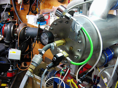
Just some general layout pictures.
Your comments are ALWAYS welcome.
Thanks
Jim
The fuel non return valve. This should stop the fuel returning into the tank and emptying the fuel filter/pump arrangement every time the engine is at rest.

This is the variable oil pressure switch which will have it's 12vdc feed taken from the fuel pump output of the relay bank so that if the oil pressure drops below 20PSI (only when the fuel pump is running) then it will trigger it's switch and send a 12vdc signal back to the Tacho board thus shutting down the engine. I will have to invert this output using a simple relay circuit because the switch is N/O (this means that when no pressure is applied to it the contacts are in the open state - it's only when you apply pressure over the set point (set with a small screw at the top of the switch) that the contacts then close so in order for it to give a 12vdc output when the pressure drops, it needs to be inverted.
Just some general layout pictures.
Over this weekend I am aiming to complete the electrical side of things for the test. Tidying up the wiring and fitting the temp controller is also on the list.
Thursday, October 04, 2007
Fuel lines in place
The copper fuel lines are now all in place with the 6mm bore from the top of the pump to the back of the nozzle and from the outlet of the prop valve to the inlet of the fuel filter.


 Fuel return from the prop valve. I may need to fit a non return valve here to stop the fuel in the fuel filter from draining back into the tank.
  The mish mosh of wiring that goes with this thing! And that's only a part of it ;)
Tuesday, October 02, 2007
Final bits to do before testing.
All I need to do now is to copper pipe the connection from the top of the fuel pump to the nozzle, copper pipe from the oulet end of the prop valve back to the inlet to the fuel filter, mend one of my starting routers as the clamp for holding in the socket fixtures I made (earlier in the blog) has bust. I think I need to get a new one! Grrrrr
I have to fit the oil pressure switch and I have a bit of wiring to complete for the fuel pump and temperature control.
It looks like it should now be in the next couple of weeks when I will be properly trying it out.
Oh - I needs to get some fuel too!!
I have to fit the oil pressure switch and I have a bit of wiring to complete for the fuel pump and temperature control.
It looks like it should now be in the next couple of weeks when I will be properly trying it out.
Oh - I needs to get some fuel too!!
Nozzle testing (again!)
I know I have already done this earlier on in the Blog but I wanted to do some final setting up of the proportional valve parameters before lift off. I wanted to make sure that open was fully open and closed was fully closed. There is a set up procedure that comes with the prop valve controller and certain steps you need to stick too to get it correct.


I used compressed air to simulate the fuel (it's a bit cleaner :) ) flow and all seemed to work fine.


I used compressed air to simulate the fuel (it's a bit cleaner :) ) flow and all seemed to work fine.


Just some pictures of the flame tube out of the combustion chamber.


 The below picture shows the CC drain hole and bung. This is to drain any excess unburnt fuel off that may pool in the bottom of the CC that could cause untold problems when you are desperately trying to shut down the engine!!


 The below picture shows the CC drain hole and bung. This is to drain any excess unburnt fuel off that may pool in the bottom of the CC that could cause untold problems when you are desperately trying to shut down the engine!!
The flame tube situated inside the CC and held in place with the FT retainer.

Subscribe to:
Posts (Atom)
